
Deep Dive
BidUnity provides the means to record trade knowledge, the understanding of the relationships between materials and labor. Being cloud based, BidUnity makes it possible to share this knowledge on an unprecedented scale. The purpose of this section is to explain how BidUnity organizes the relationships between materials and labor for determinign material and labor requirements.
Modeling Complete Building Systems
Understanding construction starts with understanding what and how, master that and you can do anything right?. BidUnity's What describes materials, labor, and other things. BidUnity's How defines the relationships between things.
For BidUnity, those concepts are logically independent. When we provide the programming to support a new kind of relationship between things, it can potentially be applied to everything else BidUnity already knows. The utility is similar to that which is derived from learning. To fully appreciate the flexibility inherent to BidUnity, lets take look at how it organizes information. BidUnity maintains everything in several independent but related layers.
Elevations | Layer #1
Elevations record size and configuration. Elevations maintain the following information.
Overall Width
Overall Height
Number of Vertical Sections
Number of Horizontal Rows
It might be helpful to think of them as empty two dimensional grids with empty space. You could also consider them to be an infinite number of such grids. BidUnity's layered approach to organizing construction information allows it to be very flexible. We are really just recording four important things here, everything else can be stacked on top or not, its in a different layer. Pretty flexible right?
Elevation Components | Layer #2
Elevation components represent patterns which can be observed in construction assemblies. Most recognizable patterns occur in three dimensional space, but some patterns do not. Elevation components organize the information which describes themselves. This includes the following information.
Location
Width
Length
Depth
Type
Our First Elevation Components
The Elevation Component
Pattern: One elevation component is required for each elevation.
Ironically, this pattern was one of the most difficult for us to discover!
What do we know about it?
Location: N/A
Width: Overall Width
Length: Overall Height
Depth: Depth of System
Type Elevation Component
Why is this useful?
BidUnity allows us to relate things to the elevation component.
Material sizes can be derived from the elevation component's width, height, or depth assuming there is such a relationship. Labor might also be assigned to the elevation for things that will need to be done, but don't repeat, like measuring.
The Vertical Section Component
Pattern: One vertical section component is required for each of the elevation's vertical sections.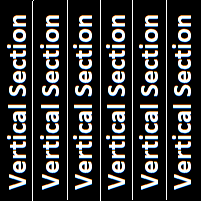
What do we know about it?
Location: 0 through the number of vertical sections
Width: Some Value
Length: Overall Height
Depth: Depth of System
Type Vertical Section Component
Why is this useful?
BidUnity allows us to relate things to the vertical section component.
Materials and labor can be related to vertical sections in many ways, but just as importantly, they will be required in the number of times which is equal to the number of vertical sections.
It might sound funny, but we think that there are other simple patterns which we have yet to find. Because we recognize the potential for more, BidUnity was designed in a way which will allow us to introduce new patterns as they are discovered.
All of these imaginary components can be programmed to follow the patterns that we observe in real objects. BidUnity derives their sizes from the elevation's dimensions and the locations of adjacent elevation components. It's like measuring a window opening to determine what size window is needed.
Type identifies purpose within the context of an elevation. Most components serve the purpose of joining adjacent colums or rows together. BidUnity relies on types to match elevation components to product system components.
To help support understanding this concept of component types, fundamental component types can be derived from the following observations.
Eight fundamental component types can be derived from unique combinations of the following attributes.
All framing components can be classified as either vertical or horizontal. Classification provides a reference axis to describe their exact orientation if other than parallel.
All framing components can be classified as either perimeter or intermediate. We found it necessary to distinguish between the top and bottom orientations as well.
All framing components can be classified as either angular or planar. Planar components relate adjacent sections to the same plane; standard mullions are planar components. Angular components cause adjacent sections to be oriented in different planes; corner posts are angular components.
Given perimeter and intermediate, lets add glassThe Glass ComponentSuppose we identify a pattern where bounded spaces are created by intersecting framing components. BidUnity understands this to be a glass component.The None ComponentSuppose that we identify an area where we don't want glass. We call it none.
Work Types | Layer #3
BidUnity's taxonomy of construction work is derived from MasterFormat. You can learn more about MasterFormat here. Work types help organize system types.
System Types | Layer #4
System types represent a category of materials so closely related in form and function that they can be considered as equal substitutes. Proposal specifications identify the system type. The system type layer includes the following information.
Glass Type: Glass types represent different glass composition types. Monolithic, laminated, and insulated-laminated are examples of different glass types.
Continuous Component Type: This identifies which of two possible patterns describes the relationships between elevation components. This concept is illustrated below.
Shim Space Deductions: Shim space deductions modify the overall size of the system by subtracting from the elevation's overall dimensions.
Receptor Deductions: Receptor Deductions modify the overall size of the system by subtracting from the elevation's overall dimensions. This does not assign sizes to receptors, it acts as a secondary shim space.
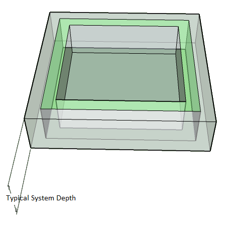
Typical System Depth: This represents the depth or thickness of the system.
Typical System Face Dimension: For horizontally oriented comonents, this becomes their observable height. For vertical components, this becomes their observable width. All elevation components are drawn based on this value. We plan to change the drawing tool from modeling at the system type level to modeling specific product systems in the future. For right now though, the sizes of real components are derived from product validations' typical face dimensions, not that of system types.
Continuous Component Types
Either of two patterns can be used to order the framework of all glazing systems. These patterns are used to assign elevation components to the elevation's grid. BidUnity will use one or the other of these patterns to locate elevation components automatically when you create new elevations. Which of the patterns are used depends entirely on the system's continuous component type. Notice that the continuous components run the full elevation length, interrupting the lengths of perpendicular components.
Continuous Vertical Components
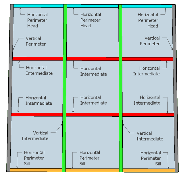
When vertical components are continuous, they interrupt horizontal components. Continuous vertical systems can have one or more coloumns and one or more rows. Component sizes are derived from the elevation's dimensions and their relationship to the other components. Storefront and curtainwall systems follow this pattern of organization.
Continuous Horizontal Components
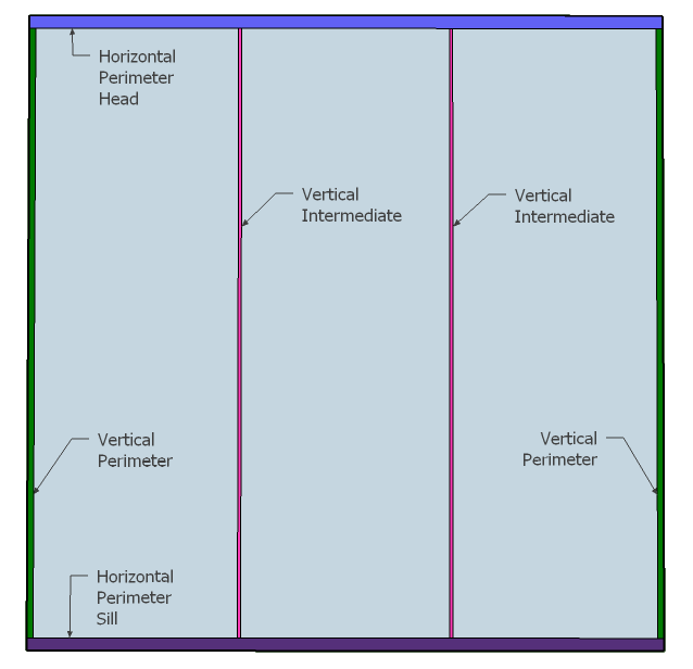
When horizontal components are continuous, they interrupt vertical components. Continuous horizontal systems can have one or more columns and have exactly one row. Component sizes are derived from the elevation's dimensions and their relationship to the other components. Mirrors, railings, showers, and top and bottom captured systems follow this pattern of organization.
Shim Spaces, Receptor Deductions, and Typical System Depth
Relating the Elevation Size to the Frame Size
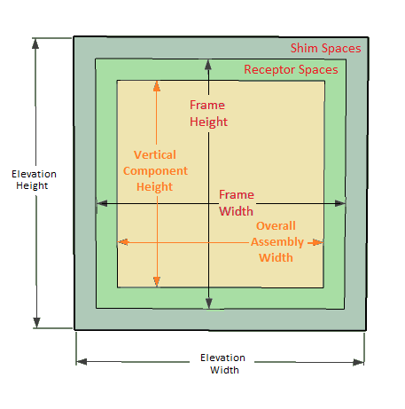
System Depth Provides Perspective
Product Systems | Layer #5
Product systems organize the methods of constructing structures and identify a primary supplier for the set of required materials. They maintain the following information.
System Type: They identify the system type.
Primary Supplier: The primary supplier is assumed to be the door supplier, usually we think of the framing supplier as primary.
System Type Information: The same information for drawing system type elevations is maintained by product systems, but here it is used to determine component sizes.
Product Validations: Product validations allow us to distinguish between available methods of building systems of products.
Product Validations | Layer #6
Product validations organize the set of components and methods available to be used in the assembly of structures. The name is borrowed from Florida's product approval process which requires systems to be validated with testing.
Product validations can have differnt types of components and even multiple, mutually exclusive components of the same types. The validation is 'built' by mapping its components to the required elevation components and recalculating their sizes to determine required material quantities. Only the components available to the product validation can be used. Product validations do not share components with other product validations, this independence allows us to organize validations based on methods of installation. Product validations include the following information.
Limitations of Use: Maximum sizes and/or pressures can be used to qualify or disqualify the system.
Approval Authority: Citation of the third party which provided validation.
Compatible Door Frame: This identifies which, if any, of the primary supplier's door frames can be used with the validation's components.
Components: Product Validations can have zero or more components.
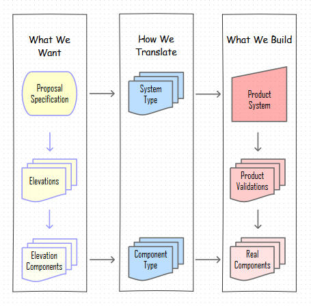
Relations Between Layers 1-6
The discussion about layers one through six highlighted the important information being recorded. How BidUnity fits it together is of equal importance.
The flow chart includes most of what we have introduced to this point.
Notice that information about space is totally contained in the 'what we want' box. Notice that information about systems of products is totally contained in the 'product system' box.
BidUnity is useful for organizing all forms of glazing work. You can begin to see how organizing systems and organizing space independently allow for each to be maintained more logically than othetwise possible.
Now that we've highlighted the separation bettween space and the systems which occupy them, lets continue.
Components | Layer #7
Components are by definition a set of one or more parts which serve a purpose within the context of an elevation. Often this purpose is to join sections of the elevation to each other. Components maintain the following informaiton.
Fundamental Component Type: You guessed it, this is how components translate to elevations.
Face Dimension: This is the observable width for vertical components or for horizontal components it is the observable height.
Other Properties: Additional information is and more can be associated with components. We've been talking about adding information to support the calculation of U-values for systems, let us know if this feature would be of use.
Constraints: Constraints can be used to disqualify components. Constraints can limit maximum sizes, pressures, and an unlimited combination of each.
Component Parts: Component parts explain how parts are used to make components.
Labor: Labor can be assigned to any of the component parts. We'll explain more about labor later.
Part Orientations
In order to support modification of components themselves an additional property is introduced.
Joining adjacent sections together implies that components themselves could be divided between sections. Therefore, it is necessary to classify the parts which make up a component. First, the component can or cannot be divided. Second, if it can be divided, which of two sides support the most accurate association.
Part orientations include three distinct cases.
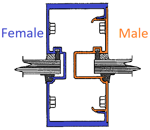
Unitary values are associated with components that are not divisible into sides. Jamb members are an example. Components which have unitary parts do not have male or female parts.
Male values are associated with components parts which nest into Female parts. Filler parts are an example. Note that Male component parts are not visible in elevation, the face dimension of male components is equal to zero. Components with Male parts should also have Female Parts.
Female values are associated with component parts which accept nesting male parts. The female section of mullion components are an example. Often the female section is referred to by the component name. The face dimension of female components is fully visible in elevation. Components with Female parts should also have male parts.
Component Parts | Layer #8
Component parts are used to associate parts with components. Component parts organize the following information.
Orientation: This identifies if and how the component can be divided into its constituent parts.
Part: The specific part required is identified.
Part Use Convention: This identifies the part's relationship to the component which results in determination of the part's size.
Quantity: This value is multiplied against the otherwise required number of parts. Note that certain part use conventions can return a multiple of items which would then be multiplied by this factor.
Addition to Processed Size: This property is added to the size returned by the part use convention, allowing for that size to be modified. The value can be positive or negative, resulting in additions or deductions accordingly.
Part Use Conventions
As the name implies, part use conventions establish the relationship between component parts and components. As previously explained, components are assigned sizes. Part sizes are derived from component sizes as modified by the convention of use. The following table further qualifies these relationships.
Convention
Value
Assigns
Per Component
One unit is required each time this component is used.
Units
Eight Inches on Center
The component's Length is divided by 8 and rounded up to the nearest integer. If minimum spacing is required from each end of the component, consider an additional Per Component association
Units
Twelve Inches on Center
The component's Length is divided by 12 and rounded up to the nearest integer. If minimum spacing is required from each end of the component, consider an additional Per Component association
Units
Sixteen Inches on Center
The component's Length is divided by 16 and rounded up to the nearest integer. If minimum spacing is required from each end of the component, consider an additional Per Component association
Units
Twenty Four Inches on Center
The component's Length is divided by 24 and rounded up to the nearest integer. If minimum spacing is required from each end of the component, consider an additional Per Component association
Units
Units Per Square Foot
The component's area is calculated in square feet. If logical, the result is assigned to the number of units required. If not logical, 10.1 screws is not logical, the result is rounded up to the next integer value then assigned to the number of units required.
Units
Opening Height
The assigned value is equal to the elevation height.
Length
Opening Width
The assigned value is equal to the elevation width.
Length
Opening Perimeter
( Opening Height + Opening Width ) * 2
Length
Overall Frame Height
Opening Height - Top Shim Space - Bottom Shim Space
Length
Overall Frame Width
Opening Width - Left Shim Space - Right Shim Space
Length
Vertical Component Height
Opening Height - Top Shim Space - Bottom Shim Space - Top Receptor Deduction - Bottom Receptor Deduction
Length
Horizontal Assembly Width
Opening Width - Left Shim Space - Right Shim Space - Left Receptor Deduction - Right Receptor Deduction
Length
Vertical Face Dimension
The Product System's Typical System Face (Dimension)
Length
Horizontal Face Dimension
The Product System's Typical System Face (Dimension)
Length
System Depth
The Product System's System Depth
Length
Interior Sealant Height
The Product System's Interior Sealant Height
Length
Daylight Width
This returns the center to center dimension between vertical framing components less the Vertical Face Dimension Observe that Vertical Face Dimension is used and not the actual dimensions of surrounding vertical components This can lead to incorrect glass sizes when a system includes vertical components of variable face dimensions
Length
Daylight Height
This returns the center to center dimension between horizontal framing components less the Horizontal Face Dimension Observe that Vertical Face Dimension is used and not the actual dimensions of surrounding vertical components This can lead to incorrect glass sizes when a system includes horizontal components of variable face dimensions
Daylight Perimeter
2 * ( Daylight Width * Daylight Height )
Length
Horizontal Vinyl Length
Daylight Width + ( Daylight Width * The Product System's Add Per Foot Vinyl / 12 )
Length
Vertical Component Vinyl Length
Behaves Differently Depending on the Component Because it Returns the Total Daylight Height of All Rows in the Component For elevations and glass there can be only one row. Vertical section components can have multiple rows. Returns the total daylight height of all rows in the component + The total daylight height of all rows in the component * The Product System's Add Per Foot Vinyl * 2
Length
Glass Perimeter Vinyl
This is the Sum of Horizontal and Vertical Vinyl
Length
Glass Height
Daylight Height + The Product System's Actual Height minus Daylight Height
Length
Glass Width
Daylight Width + The Product System's Actual Width minus Daylight Width
Length
Glass Block Area
Returns the Area Given By Rounding Each of Glass Width and Glass Height Up to the Nearest Even Inch The Length and Width are stored as cut-size dimensions
Area, Length, and Width
The Elevation's Total Width * The Elevation's Total Height, Units are Converted to Square Feet
Area
Caulk Joint Depth
The Caulk Joint Depth is 1/2 of the shim space if this is less than 1/4, then 1/4 if this is more than 3/8, then 3/8 This is used to calculate the volume of caulk joints
Length
Exterior Perimeter Joint Volume (x2 for waste)
One-Side Perimeter Joint Volume (x2 for waste) + (Product System's Interior Sealant Height * Caulk Joint Depth @ Right * Right Shim Space) + (Product System's Interior Sealant Height * Caulk Joint Depth @ Left * Left Shim Space) + (Opening Width * Caulk Joint Depth @ Bottom * Bottom Shim Space) This result is converted to mL
Volume
Glass Perimeter Joint Volume x System Properties
Daylight Perimeter * Product System's Structural Sealant Width * Product System's Structural Sealant Depth This Result is Converted to mL: 16.387 mL / in^3 This Result is Multiplied by 1.25 to Allow for Waste
Volume
One-Side Perimeter Joint Volume (x2 for waste)
Sum: (Caulk Joint Depth * Shim Space at this side * Length at this side) For Each Side of the Elevation The result is converted to mL from cubic inches by multiplying by: 16.387 ml / 1 in^3 This result is multiplied by 2 which compensates for waste.
Volume
Exterior Perimeter Joint Volume (x2 for waste)
One-Side Perimeter Joint Volume (x2 for waste) + (Product System's Interior Sealant Height * Caulk Joint Depth @ Right * Right Shim Space) + (Product System's Interior Sealant Height * Caulk Joint Depth @ Left * Left Shim Space) + (Opening Width * Caulk Joint Depth @ Bottom * Bottom Shim Space) Again, the result is converted to mL
Volume
Parts | Layer #9
You would think parts would be simple, but they might contain more information than any other layer.
Material can be measured and used in several, but not infinite ways.
In the glass industry, things are measured by...
Unit
Length
Area
Volume
Weight
Time
In the glass industry, materials are consumed by...
Unit, without waste
Exact Length, without waste
Stock Length, with cutting loss/waste
Stock Length, with negligible cutting loss/waste
Area, without waste
Area, with cutting loss/waste
Volume, without waste
Volume, with loss/waste
Weight, without waste
Weight, with loss/waste
The finite number of ways that materials are sold and purchased is derived from how they are measured and consumed.
In the glass industry, materials are purchased by...
Unconstrained Unit: One or more units is ordered at a time.
Constrained Units: A minimum number of units must be ordered at a time.
Unconstrained Length: A specific length is rendered to order.
Constrained Length: A discrete or 'stock' length is ordered at a time. Cutting patterns should be optimized for this type of material. A minimum number of units equal to 1 or more must be ordred at a time,
Constrained, Spliceable Length: A discrete or 'stock' length is ordered at a time. Cutting patterns are not optimized for this type of material. A minimum number of units equal to 1 or more must be ordred at a time,
Unconstrained Area: A value is assigned per unit of area. The actual and chargeable areas are related, but not necessarily the same.
Constrained Area: A value is assigned to sheet goods having specific length and width.
Unconstrained Volume: A value is assigned per unit of volume.
Constrained Volume: A value is assigned per fixed number of units of volume.
Unconstrained Weight: A value is assigned per unit of mass.
Constrained Weight: A value is assigned per fixed mass.
Labor | Layer #10
You can associate labor activities with parts to organize the durations of each part of the work.
Doors & Door Components | Layer #11
You can learn more about doors in the section that discusses them.
Accounts & Accounting | Layer #12
A detailed taxonomy of accounts is provided for tracking everything.
Last updated